Showing posts with label structures. Show all posts

Wednesday, August 9, 2023

Day 21. All in all it’s just another brick in the wall

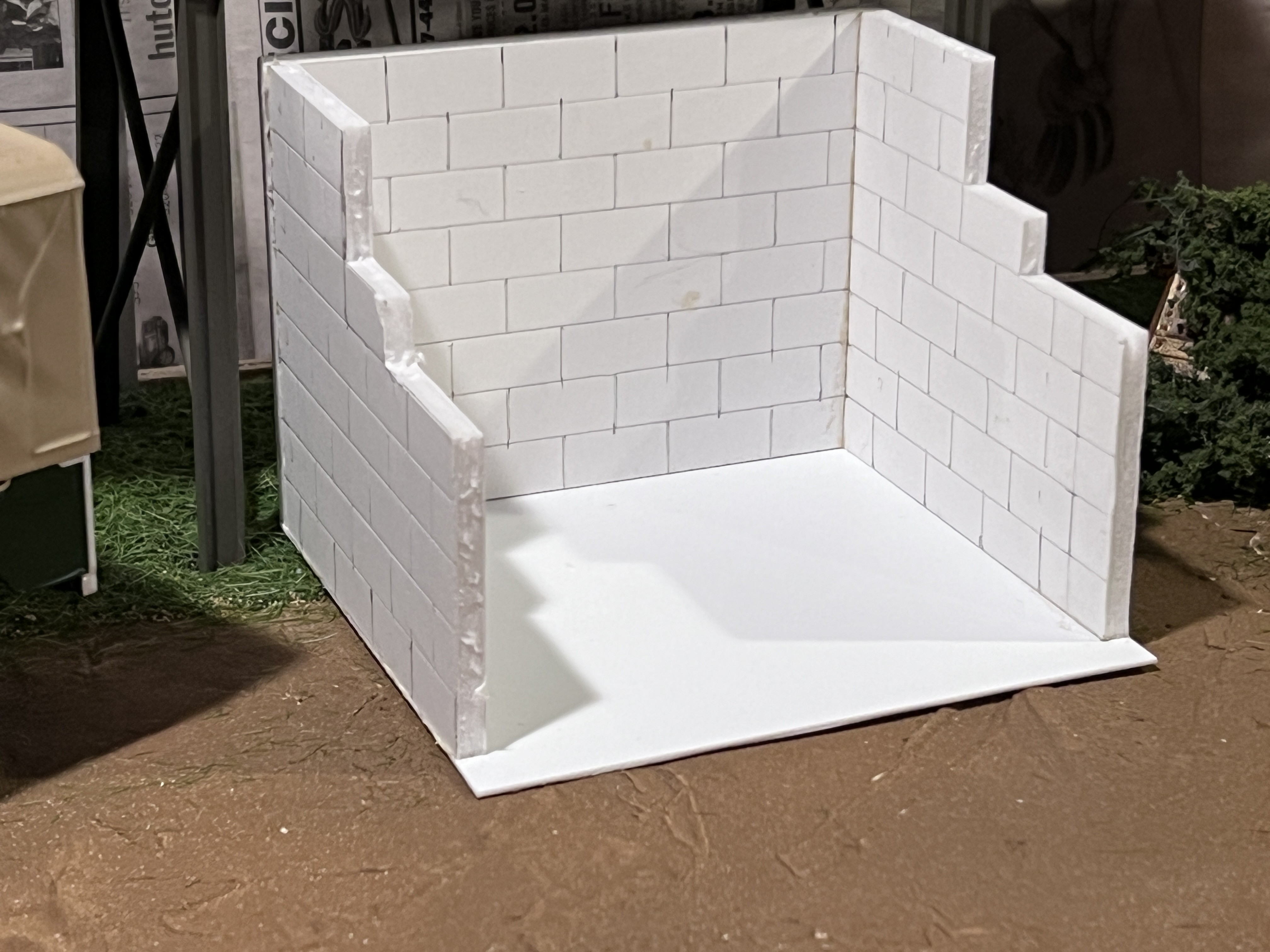
Those were the words running though my head as I was putting together the sand bin for the layout. You can see why… I marked out the courses to help me see them as I scribed the board. There’s no doubt about it. It’s a Pink Floyd Wall. 
So they weren’t bricks in the wall they were breeze blocks
I have been thinking about the sand bin for a long time. What’s the best way to model it? This is 16mm scale. The breeze blocks (cinder blocks) such a bin would be made from have size. Approximately 22mm x 11mm x 11mm in 16mm scale. So there’s no cutting corners really. 
This is my first attempt at recreating the bin. Using foamcore board. This board is too thin to represent the older thicker concrete breeze blocks. But it’s the correct thickness for the more modern, lighter, cinder blocks. So it might work. This is going to be something that will be moved on and off the layout as it gets filled. So it also needs to be quite sturdy and to take the weight of the Woodland scenics ballast that I will be tipping. Some testing of how much handling the bin will take is needed.

There’s one other thing that the structure looks like in its current state. A urinal at a lower league English Football ground…

Friday, July 28, 2023

Day 14 (or so) Bins

What I really want to be able to do on this layout is to empty the contents of a skip into the back of a truck. A long search, accompanied by helpful advice on the NGRMOnline forum, has sourced some good ideas for suitable builders lorries to receive a load. However, one particular manufacturer is quoting 2 months delivery on an item, While another would appear to be reticent about delivering to the USA. (To be honest, I don’t blame them. The transatlantic mail service is not what it used to be.) So, I’m giving consideration to making a bin to tip into, while I wait for a lorry to arrive from wherever it may be. 
From the outset I’ve been considering the concept of tipping different grades of sands or gravels into different bins. I thought perhaps three at the start, now I think only two different grades would be needed. To that end, I started to mock up the size of bin that would be needed. I’ve no idea how this feature would translate into 16mm scale so mock ups are a must.
Mocking up the bin
As you can see, once you add the Land Rover and a bin, the area starts to fill up. I think I could only get away with the one bin on the layout. A few millimeters here and there in the size of the bin are going to  make all the difference. Proportions of height to width, are important. If you make it too tall and thin it’s going to look flimsy and like the walls could collapse under the weight of sand. Too short and fat and the sand or gravel will spill out of the bin as the amount tipped into the bin increases. 
How much gravel/sand will a bin hold? How much spillage outside the bin will there be?
A mock up and test is needed.
The bin holds a lot of sand/gravel
Successful tipping experiments
What this tells me is that despite the long drop there is no overspill. Perhaps as the bin fills up the chance of material ending up outside the receptacle would increase but right now I’ve emptied 6 skip loads into this bin and there’s no overspill. I’ve also run out of fine buff ballast so I can’t add more. I think that’s a success.
I’ll add a handle to the back of the bin so I can easily slide it rearwards off the layout to be emptied or perhaps even change it out with a lorry when it is full. All in all, a successful days work.


Monday, July 24, 2023

Day 11. Railings

I was pretty nervous about this project, so I spent quite a bit of time working out the best way to complete it. 
In smaller scales of course, you just go out and buy some fencing to suit. If there’s anything in 16mm scale I couldn’t find it. So scratch building was called for.  
I did my due diligence, researching dimensions and sizes. I wanted to use styrene tube for the posts and rail. In the end it turned out I didn’t have any tube in the size I wanted. I had lots of 2.5mm rod though, and it looked like it looked right. So rod it was. I’d just have to drill a few extra holes, that’s all. These extra holes were going to be in the end of the rod though. But as I had already drilled out rod when working on the exhaust pipe for my “Huddy” I wasn’t phased by that. The first thing I needed was a jig.
Another task, another jig.
Pretty much every job on the layout has needed a jig somewhere to aid its construction. This one was no exception. Sections of strip wood hold the rod in place, and allow me to cut the rod to the correct length. A section of the corrugated sheet that I used for the sleepers had holes drilled in it at the correct distances for the safety rails. This should, in theory, give a batch of identical fence posts, and it pretty much did.
All identical (or pretty close)
A hole was drilled in the end of the fence post, to accept a short length of .75mm rod to locate it in the deck and similar lengths of the rod were placed in the holes on the post to help locate the rails.
From then on, it was pretty simple. Yes you had to be careful, but as all the rods had been cut to the same length and drilled correctly it all went together quite easily. I didn’t even need a jig for this stage of the project. Before long I had a pretty good looking section of safety railing.
First section. Yes, I’m feeling pretty pleased with myself.
The second section was a bit more challenging. But not much. It involved a right angle turn in the railing to enable it to go partly across the end of the deck.
But simply with careful drilling and lining up of the holes the pins were easily placed to make the turn possible.
By now, I’m feeling invincible
Some holes were drilled into the deck and the safety rails were put in place for the first time…
Well, what can I say?
Even the right angle turn worked out.
A quick spray of paint to cover the white and job’s a good’ un
Needless to say. I’m feeling pretty pleased with myself. This is something I’d never needed to do before. It was something that I didn’t have the foggiest idea how to do. There may even have been an easier way to do it. Though I’m not sure that just butt jointing the sections of post and rail together would have resulted in as good a join as I have this way.
The lesson everyone can take away from this is never be afraid to try something out of your comfort zone. 

Day 10 - some thoughts

(A day late sorry)
Sometimes you don’t realize how long you spend thinking about tasks on a layout until you actually start logging your time. 
Like with these daily blog posts. I look at the work I’ve done, and yes, some of it like cutting the deck of tipping dock. Took a heck of a long time. 
But then there was the working out how to make the jig for the yard fence. I swear that measuring up and working out where all the stops and supports went took longer than the actual assembly of the fence sections themselves. I may have already made a mock up of the wagon loading chute, but there’s a drawing being done to help me make the actual thing. The safety handrail for the dock is another thing being worked on. There’s a lot of time being spent thinking.
I have pieced together several drawings for projects for the layout. I use an app called Graphic. They help me visualize the construction and any problems that might occur. They may, or may not, depending on the structure, be to scale. They may, or may not, depending on the finished model be an accurate copy of the prototype.
Tipper shelter, so many things to work out. So much head scratching.

A drawing for the tipper shelter was a case in point. It was an absolute must. The prototype was so flimsy there was little to go on from the prototype photo. In fact the whole thing didn’t come fully together until I worked out how to make it stand up by itself. Which I couldn’t do until I saw the finished shelter.
A full size drawing didn’t help work out how to stand the shelter up.
The Handrail is not a difficult task. Not compared to the shelter or the forthcoming loading chute but it still needs a drawing.
Handrail details
I need to visualize how to actually construct the thing. How do I fix the rails to the posts? How do I fix the posts to the deck? This quick visualization explores the idea of the construction of posts from styrene tube, with a section of rod glued inside them as pins to locate them in the deck. Similarly, the rails will be located in place thanks to pins through the posts. Now I need to spend more time figuring out the jig to drill the holes in the correct place. I hope that once I get through this next batch of thinking time I’ll be able to get started on the handrails soon.


Saturday, July 22, 2023

Day 9

After a little respite yesterday to review one weeks work. It’s time to move on again. I will try set out with the aim of working on an item for the layout a day. Working during the week on bite sized chunks to keep things progressing. There’s things like the fence, the handrail around the tipping deck, things like that. To that end I decided to start with the short section of fence around the end of the dock. It was simple enough to find drawings on the internet that showed the dimensions of a simple three rail fence. 
First up I needed a couple of simple jigs to get the same sized parts to fit the same way.
It might not look like much, but this simple arrangement of stripwood and foamcore board is the key to getting all the parts to fit.

This is how it holds all the parts together.

The assembled fence. Next a quick wash with alcohol/India ink.

In place and ready to be bedded in
One more simple job done.

Friday, July 21, 2023

The eighth day review.

After one week on the project, I thought it would be good to sit back and take a look at what happened in the previous seven days. This is an overall view of all 4’ x 14” of it.
Overall view
Yes. I know that at 4’ x 14” it’s over the four square feet maximum. But putting on my ‘Editor of the Micro Model Railway Dispatch” hat. I’m always happy to give larger scales line 16mm and 7/8ths some leeway. It’s still most definitely “in the spirit of a micro” as Carl would say.
Let’s take a look at the progress of the scenes.

The skip loader in a sand quarry setting. It’s difficult to to put over the effect of a full-blown sand quarry in a couple of square feet. But a few piles of sand will help. As for the “sand”. How do you model it in 16mm scale? 
I’ve no idea, but this is how I’ve started. After I’d covered the contours with spackle, I painted the surface a cream colour, just in case whatever I chose to represent the sand came off exposing the base contours.
The first ground cover was Woodland Scenics “yellow” turf, that looks more like a green. This was sprinkled on a smothering of white glue. Then I ballasted the track with Woodland Scenics buff fine ballast. It’s starting to look OK but some more sand is needed. It feels like Steve Bennett’s early layouts.

The other end of the layout has a totally different feel to it. More conventional in its scenic treatment. There’s going to be a lot of scrub and weeds and such underneath the tipping dock. Right now the two scenes are separated by a retaining wall. It might have some vegetation growing over it, it might help to blend, yet separate the two scenes. I am very inclined to add a small shed of some description leaning against it. But probably not a prefabricated concrete garage.
At the end here, a fence and gate is planned, perhaps with a premises sign. 
The previous two pictures also show the problem with vehicles in this scale. The Land Rover is a small vehicle and yet it’s eight inches (200mm) long. I wouldn’t want a vehicle much longer than this in there. I did find a 1:20 scale toy garbage truck that could probably could have been worked into a lorry. But it was 15” long, as the layout is 14” deep so fitting it in would be rather difficult, if not impossible.
So that’s it then. One weeks work. Still lots to do, but lots to keep me interested.
Oh, one last thing. How did I get the incredibly flimsy tipper shelter to stand up? This rear view should clear things up.
How to stand the shelter up. Extra long legs hidden behind everything


Thursday, July 20, 2023

Day 7

Day seven. Technically that’s one week since the project started. From the outset, I doubted that I could build a 16mm scale layout in the time frame. I’ve come on a long way though. It’s definitely starting to look like a micro layout. How does the old adage go? The last 20% of a layout’s construction takes 80% of the time? I’m getting perilously close to starting on the last 20%.
One thing that has been causing much head scratching has been the shelter for the tipping point. In the photograph I have, the structure looks flimsy. Very flimsy. It looks like it would get blown away in a strong wind. I’ve since had it confirmed to me that these structures were not to the strongest construction. The problem was to be recreating that flimsiness while building a structure that will withstand trips to model railway shows. 
With only one photo to work from and no dimensions. A lot of guesstimation was involved. I had a feeling that to keep things simple, the shelter height was the same as a sheet of corrugated metal (why waste time cutting things?). The standard sheet height was eight feet. The internet also told me that a sheet was about 28” wide. Knowing that there would also be a one and a half corrugations overlap between sheets helped calculate the length. I had some corrugated sheet that looked right and cut it to size. After that, I searched through my stock of styrene girders and found stuff that, once again, looked the right size. There was even more guesswork attached to the roof. But no-one will know. Besides, I probably used the same frame of mind in the construction of my model as the man who built the original.
My take on the tipping shelter. It looks good enough for me.
As for looking flimsy, but being sturdy. I’ve accidentally dropped it a couple of times and it has survived each fall. Job done then.
One job I hadn’t done yet was to bed in the tipping dock. I’m surprised I hadn’t done it as soon as the rails were laid on it. Because that meant I could run a train on there. There’s still lots of work to do on the tipping dock, finishing off the shelter of course, hand rails around the edge and a buffer stop at the end for starters.
But that shouldn’t stop me fitting it in place and trying things out…

You know you wanted to see a run of the train on the layout… 
The Motor Rail uses Chris Rennie’s LocoRemote WiFi system. Right now I’m perfectly happy with it. The big thing is there’s no wires to the track and the rails can be as dirty as you like. The trains will still run.
I suppose that you could say that with trains running and some scenery in place, I have built a layout in seven days…


Sunday, July 16, 2023

Day 3.

 I left the decking overnight hoping that it would be likable in the morning. It wasn’t. I gave it another wash of a lighter grey to kill the blue tinge of the darker wash. Then let that dry. 
It’s not too bad now
It’s better now. I’m looking at it from directly above, an angle no-one will see it from. 
While this dried, I started work on on the legs and support frame. I have expended much brain power on working out the best way to assemble all my sections of Plastruct girder to make something that looks like the prototype. I figured a pattern of some sort was in order to make enough identical supports.

After a few hours I had five pretty identical legs.

This may well look like a wooden fence, (something to bear in mind for the future) but it is actually the timber deck for the tipping dock.

Another day finished. I expect tomorrow I’ll have to lay the rails on the decking before assembling the substructure. What else will I have time for?

Wednesday, July 12, 2023

Tipping Talk

There’s only two structures on the layout. The garage/workshop and the tipping dock. The garage/workshop was outlined in the previous post. Now let’s discuss the tipping dock.
I was inspired to build the layout by the picture in issue 134 of The Review. So the structure has to really look a lot like that. So far I have only found one other picture of it. Tucked away in the background of a photo by Gordon Edgar on Flickr
Handily, it’s an end on shot so it gives another angle on the structure. 
End on in the distance of Gordon Edgar’s photo
I scrutinized this picture and the one in The Review and I think I’ve manage to come up with an arrangement that I’m happy with. It’ll be adjusted to fit the location of course, but it captures what I’m after.
Possible arrangement of Garside’s tipping dock
I think it looks like a quite passable representation of the actual thing. I’d appreciate any thoughts and feedback on my interpretation. 


Tuesday, July 11, 2023

In praise of the prefab concrete garage

With the general idea of what the layout should look like. I did some more measuring out. To see how things would fit more precisely. 
I’m looking for a pleasing vignette in this area.

The yellow grey board is the footprint of an archetypal 8’ x 16
’ prefabricated garage. The sort of thing that was very popular in the UK from the post war years to the late 1970’s (see below)
The prefabricated concrete garage is one of the forgotten mainstays of English society in the late 20th century. To go with the post war motoring boom everyone wanted a garage to house their beautiful new car. These pre-cast concrete panel kits were cheap and plentiful. Marley, Kencast, and Dencroft were almost household names. They could be “put up in a weekend with the help of a friend”, as one manufacturer said in their advertising. One of my Grandfathers had one. I’d really like to fit something like this on the layout. It would be the perfect thing for a small industrial narrow gauge railway to use to service and store their rolling stock. 
The standard size of a garage back then was 8’ x 16’. So, I cut a 16mm scale floor pan to see how it would fit on the layout. It fits as you can see on the photo above. Depending on its position, it may need a little cut out to fit within the track clearances. But it would fit in. But would everything fit in the garage? Another mock-up was called for.
Things seem to fit. It might be a bit cramped. But what garage isn’t? 
It would fit two small locos. The garage looks like it’s a going to be a project then.

Thursday, January 26, 2023

Pause, reflect

I've reached that stage.  I'm the vast majority of the way through the layouts construction. It's just detailing work to do. I can add bits and pieces here and there to my hearts content to make the scene looked lived in. Like a place of work should. There's so many little things to be done, or could be done. But what? Time to pause and reflect. Here's some things to think about.

To do: Detail the workshop with tools and other rubbish. Perhaps a delightfully dated, (maybe some will say sexist), pinup poster on a wall. The workshop will need properly bedding in, like all the structures on the layout. In the future, I may also run a short section of panel track into the workshop to model a wagon under repair.
 
To do: Do I need to do more? I could add pipe, or girders, bag of cement, and even more wood to a pile of workplace junk. But would it achieve anything extra to what's already suggested here?

Quite a nice vista. Not a view that the regular layout viewer would see.
To do: Anything? Right now I can't think of anything much. A new viewpoint like this can make you think. How about a rack of steel sections in front of the sheeted over items maybe?

To do: Why is that ladder up against the gutter? Is he going to clear the gutters out? I once had a sunflower growing in one of the gutters of my garage. Weeds in the gutter to add to the scene then. The door does need a handle though.

Just messing around. To do: More tension needed in the weighted down ropes that hold the tarpaulin in place.

This is good. Seriously, I might not ever top this as a vignette where I set out to do something and achieved what I set out to do. Nothing else needed here.

Aerial view. There's a surprising amount of space to fill. If I wanted to, that is.

From this view you can see all three tracks, as set out on Carl Arendt's original Squarefoot estate railway layout.
I have a couple more Binnie skips to build, and as you know I plan to model those as fairly new and free of damage. There's a Motor Rail kit coming from LocoRemote too. Then there's an 'Issing Sid kit to build for fun. All those items will need painting, and it's too cold here in Minnesota to go down to the garage and spray paint things right now. Perhaps I will have to wait until March to do that job. The only truly major task to do is to devise the tipper to fill the wagons. I have a few ideas on that, it just needs fine tuning to fit the location. So perhaps there won't be much activity on here in the coming weeks. We'll see. 

What do you think I could add? Reply here or wherever you were referred from, either Facebook, NGRMOnline, or Voie Libre. I'd be interested in feedback. 

*It should be noted that the figures aren't painted for a reason. My wife wants to paint those. So I'm leaving them well alone.

Friday, January 13, 2023

Real progress

 The relative success of creating the workshop really spurred me on to make further progress on the layout. 

General overall view. I was planning a tall hedge behind the workshop. But I think a brick wall is easier.


The workshop interior. The up and over door feels right too. A short length of rope hanging down to facilitate the closing of the door will set it off perfectly.

Debris and detritus around the yard will help create the right feel. I might also run a disconnected length of track into the workshop.

Aerial view

The brick base to the building really makes this. The door adds something too, a big improvement on the plain wall previously.

The view is layered, creating more depth. Final positions of scrap  to be decided.


*Fy Merlen Bach*

Winter is coming…The phrase that spawned hundreds of cringeworthy internet memes. To me it means that any model making I do will be confined...