Showing posts with label construction. Show all posts

Tuesday, October 3, 2023

What to do next?

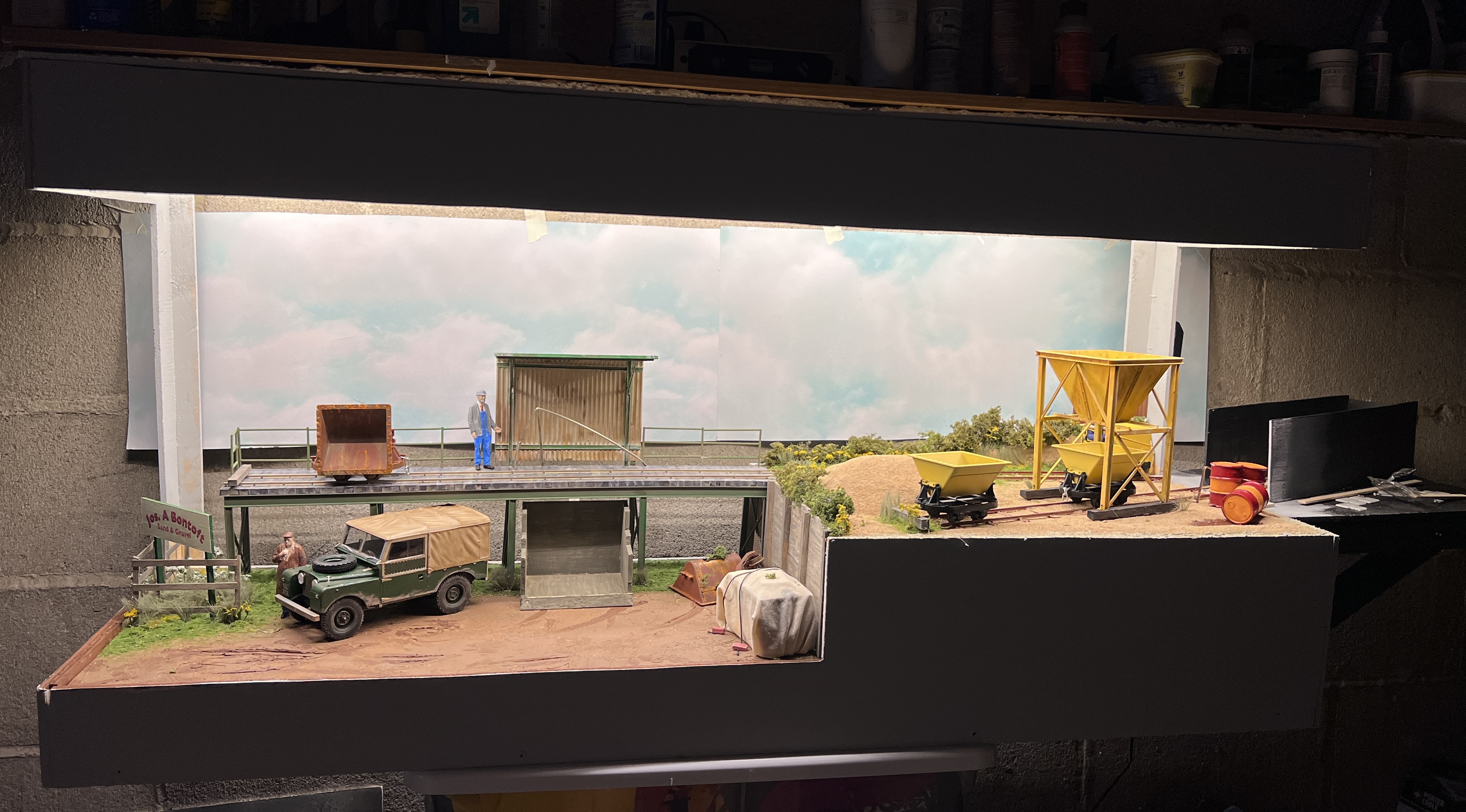
Three weeks to the layouts debut. The layout is essentially done. Now it’s just looking and finding things to do. Things like:
The rails here should be rusted.
After the euphoria of getting the chute to work had settled in. I began to think that it needed support legs so it didn’t hang in the sky so much. That needs some thought.
How to get the trains around the legs though?
Weeds and grass. I have lots of tufts. I could add a plenty more here and there to get the overgrown effect. Some places do need it.
There’s room for a lot of weeds on these bare patches
Weeds around this bin would help locate it in the right place after every emptying


Friday, September 29, 2023

95%

Not much left to do

Is the layout 95% complete? 99% perhaps? I don’t know. All I know is that there’s pretty not much left to do. I sit in front of the layout and loose myself in it. Trains running or not. 
As you know, in the past few days, I was very frustrated with the tipper actuation rail. So I worked on other things to take my mind off it.
The first sector plate cassette has been built. It was made from 3mm aviation modellers plywood. On reflection this might be a little too thin and I’ll build the next one from something a bit thicker.
Plywood base and strip wood sleepers match the rail height on the layout perfectly
The cassette was painted grey fading into black to match the fiddle yard. 
This makes it less noticeable as you can see in the top picture..
The layout lighting is now in place. I had been very impressed with the LED strips that James Hilton uses on his projects. I bought some from Amazon. Sixteen feet in length complete with dimmer controller for $16. It is also self adhesive backed and comes with clips to fix it in place as well. I shall use those and add a few more of my own as I’m pretty certain that glue won’t stay stuck forever. A dollar a foot and I only used 10 feet. A bargain for sure. The lighting is very even. I like it a lot
First fitting of the LED strip
Hidden behind the barrels at exit offstage is the bumper to return the skip buckets to their correct position. Making this was much easier than the tipping rail. You can’t see it, which adds to the mystery.
You can’t see the tipper rail, can you? In other matters, health and safety will surely have something to say about the spillage there. 
There it is
A backscene is still needed, and though the cloud scene in the pictures looks pretty good. It actually has a greenish tinge that is quite unattractive to my eye. I might search out a better sky paper, or I might go for a plain neutral blue grey like the cabinet.
The final thing is to find a novel way to tip into the wagons at shows. Right now I just spoon a material into the skip buckets through the chute. It works. But a shows something more entertaining should be used. Something like this would be perfect. But at 1:16 scale it might be a tad too large for the area it needs to fit in. Perhaps it could be converted and adapted to fit the site in front of the sector plate.
Anyway we keep plodding along. Like any marathon I run, the finish is in sight.

.


Monday, September 18, 2023

Back in the saddle again

We are back from our holidays in England and Wales and suitably refreshed. I am chomping at the bit to get on with the layout. I know that it is very close to being “completed”. So I made a short list of things that need to be done. As you can see, it’s a pretty short list.
Things to do
The LED strip lighting has been ordered and will be here on Thursday. It’s one of those rolls of LED’s on a self adhesive strip from Amazon. So I’ll look forward to dealing with that next week. 
Something I could do that would really start to set things off would be to paint the display case. I’ve ummed and ah-ed about the colour of the case for ages. I knew I wanted a light neutral colour. I was thinking about a sandy tone. But in the end I went for a neutral blue-grey. “Shallow Skies” in the Valspar oeuvre. It’s a colour that I could carry on to a backdrop for something un-noticeable. 
The neighbors son works in the hardware store in town, so he mixed me up a quart of the stuff, and I ran off to the garage to slap the paint on. Bingo! In a few hours around lunch the case was transformed.
The case, painted.
That’s it really. I shan’t bore you with writings about painting, everyone knows how to paint. Instead I’ll finish off with a few holiday snaps…
The Goodwood Revival. The best historic motor racing in the world
My wife and I, and a Class 31
On the Ffestiniog Railway.
A second trip on the Ffestiniog, and another double Fairlie
The Jack Nelson LNWR dioramas
It’s good to be back.

Tuesday, August 22, 2023

Traversing

 I’m officially stopping counting the days of construction now. The layout is now at a state of completion where it could go to a show as it is, or with minimal extra work done. Besides, I’ve seen layouts at shows in worse state of completion. So I’m happy with no more counting. We’ll call it 30 days and be done with it. 
I’ve had a couple of questions asked about the construction of the sector plate/train storage. As this is still a work in progress towards a finalized design, the details of the cassette are still under consideration. But, as the most important part of the sector plate is lining up the roads correctly. I can at least offer some views based on my experiences with that.
1. The single most important thing in marking a sector plate is finding the pivot point. That way the track centers line up, and the curved end of the sector plate can swing and not foul anything on the layout, (been there, done that).
It also goes without saying that if you have a curve going into a sector plate you’re probably making unnecessary trouble for yourself. Much like having flexible track joins on curves.
The tracks on my layout are dead straight, so it’s pretty easy to run a ruler along the inside edge of the rail and trace it back on the deck of the baseboard as in this top picture.
2. You draw lines from both sets rails back on the baseboard. Find the middle of them, draw those lines back, and where the track center lines intersect. That’s the pivot point. You should also try to draw as few lines as possible doing is. As you can see I drew plenty of lines, and mis-marked the centre. Which I didn’t discover until I tried to make the deck of the sector plate. 
3. Make a template for the sector plate deck. Decide what size it’s going to be. Cut some material or other (I’ve used foamcore) and mark a curve based on the radius you want from the pivot point. I went for 12” (305mm) on mine, working with the layouts T.L.U. (Train length unit). You might, like I did, have to mark the curve on both the layout and the sector plate deck. I trimmed the edge of the layout to the curve and then the sector plate deck template to the same. It should match pretty perfectly. Now the real test. Pin the sector plate deck though the pivot point. If you’ve done this right, the sector plate should swing perfectly across the baseboard edge. This was where I found out that I had drawn too many lines and marked the wrong pivot point.

4. & 5. The moment I realized I had the wrong pivot point marked. In the top photo everything lines up perfectly. The bottom one leaves a HUGE gap. So it was back to step 1. Re-mark the track lines and centers and carefully mark the new pivot point. This did necessitate a slight trim of the scenery but not much.

6. & 7. Now you can see that everything lines up perfectly. The curved faces of the sector plate and the baseboard meet perfectly. All I have to do is trim the rails back.

8. & 9. Look along the track and you should be able to make out that the rails and the lines of the track on the sector plate deck line up, and the perspective continues seamlessly.  
If you’re feeling brave there’s one last thing you can do to prove that everything is aligned perfectly. Line the deck up with the tracks on the layout. Put the pivot pin (I was using a T-pin) into its hole on the deck and it should drop straight into the pivot point hole on the baseboard. 
There, that’s how I did it. I hope that wasn’t too “how-I-blew-my-nose” for you. But I did go through multiple steps to make sure I did align things correctly.
Now I can finalize the design of the cassettes. They will probably be made from 3/16” (5mm-ish) ply. The pivot and hole will be a bit larger than T-pin size though. 
Finally, for those who are concerned about the cutting away of the baseboard surface to get the curved faces to align. This will be what you can see on the layout. 
If anyone has concerns about sector plates, I hope this eases your fears. I did over complicate things with mine, I thought I had such a good idea, overlapping the sector plate onto the baseboard to help with baseboard join alignment. But perhaps not, I got there without too much problem in the end though. 
I’ll see you another day.


Monday, August 21, 2023

Day 27-28-29 Building the fiddle yard.

This was always going to be a tough one. I was dreading this more than anything. Adding the sector plate. Making something fit onto the end of the layout. It didn’t need to me much more than a foot square. In the end I went for 13” x 10” (330mm x 250mm). 
On the face of it it was a simple task. Build the frame, put a surface on it, (though that’s not entirely necessary, I just felt better putting one on) and set up the joining of it to the main section case.
Woodworking is never simple with me. You’ll recall my shock at competently building the case. The project used up all my good luck. It was downhill from here on.
Making the template for the fiddle yard end.
I shan’t recount the problems I had. Cutting wood to the correct length, getting the correct angles on the support struts. Even drilling holes for the screws was a problem. I stripped a couple of pozi-drive screwdriver tips and screws. I was at the point of quitting.
“If this screw doesn’t go in, problem free, this time. I’m quitting for the day” I was in the depths of despair. If the screw hadn’t gone in. I would likely have been in tears. Luckily it went in. It’s a shambolic piece of woodworking. But it is on there. Flat and level.
I hope you can’t see all the cock-ups.
I can console myself with the thought that the list of things to do on this layout is now so short, that the layout is almost finished. The wagon loading funnel needs rivets adding and painting, then it can be installed on the layout. Lots of detailing bits and pieces, (a never ending task). 
A system for the unloader needs to be devised. I know it can easily be done by hand. But I don’t know wether to do a hidden manual system or automatic tipping rail. I like to be “hands on” in operating the layout. I could do a simple hidden “pusher” to tip the wagon, or I could try to devise a more complicated system, where a figure could be seen to be tipping the wagon by hand. That would be neat. That would need some serious thought. 
Finally, the train cassettes need to be designed. I’d like an individual cassette to each train. One that could act as storage and protection away from shows, as well as during. I’ll probably have to design and make a few prototypes first. I have some ideas on this. On the strength of the past few days work, they certainly won’t be wooden ones. 

Friday, August 18, 2023

Fiddle yard thoughts Day 26-ish

Much thought has been devoted to the form that the offstage area will take. I have to stop calling it a fiddle yard. That suggests something far grander. I’m just in need of a small area to switch out train cassettes and switch between the two roads. 
After some consideration the best arrangement would be something like this.
Set up sketch
The drawing makes reference to an angled face needed due to the cutaway of the foam baseboard. This photo shows what I mean.
The join area
This was a bit of a cock up at the time. I was looking at the wrong end of the raised area as I lined things up and let the glue set. But right now it doesn’t look so bad as the tab will assist in the location of the offstage area. The rails need to be cut back a smidge, and a little curve cut in the foam, But it should all be good in the end.


Tuesday, August 8, 2023

Day 20. Casing the joint.

It had to happen sometime. The display case had to be started. As the layout progresses, the time when all my hard work needs to be properly protected becomes more important. Case in point being yesterday’s incident with the tipping dock. Not that a protective case would have helped in that instant. I just don’t want to go through any more repairs to things. So the case had to be built.
As you know my woodworking skills are severely lacking so a monumental task like this has to be done when I am in the right frame of mind. Perhaps yesterdays occurrence helped in that regard. But as I started marking up the 1/4” ply. I felt pretty good. Then I started checking and double (event triple and quadruple) checking measurements. I measured a distance in inches and then the same distance in millimeters. 
I may have mentioned before that I have dyscalculia, so any dealings with numbers are fraught with issues. It was tough. Dyscalculia is not number dyslexia. It’s difficulty in dealing with the processing of numbers. Basic addition is OK. Anything beyond that and I struggle. Anything smaller than an eighth of an inch, and forget it. If course I should be working in metric, (Dammit so should America). But when everything is measured in imperial, converting is hard work and mentally exhausting.
But after a two and a half hours, I had cut 5 pieces of plywood to the correct (or near enough correct) shapes and sizes, and much to my amazement everything seemed to fit together. 
Front left view
Front right
From the rear.
After a few hours sitting and staring at the photographs and thinking things over. I have come to the following conclusions:
1. I don’t know how on earth I managed to get this all to fit together.
2. The rear uprights are only 2” deep, they should probably have some bracing against them in order to keep the structure rigid.
3. The split ground level is problematic. The window depth is about right when looking at the higher ground level. But very deep at the lower level. 
4. I wonder if an extra brace at the front would be needed. A thin piece of barely noticeable tube giving extra support. (The front right photo seems to show something like that, with the way the shelving unit behind it lined up).
5. Lighting inside the frame/box. Some four foot lengths of 2” x 1” or smaller, running the length of the layout with LED light strips like these affixed to them to light the layout. Would they also help hold the cabinet square?
5. I rested the layout on our grill to take the photographs. The track level is 58”.  I like the height.
6. Still undecided about what to to about the backscene. As I prefer to be “hands on” with the operation of the loader, tipper and couplers an open back is preferable.
7. Seriously, how on earth did I manage this?
Now, the next task is to work out how to fit a sector plate/fiddlestick to the side. Though I might wait a couple more days before doing any more woodworking.

Friday, July 28, 2023

Day 14 (or so) Bins

What I really want to be able to do on this layout is to empty the contents of a skip into the back of a truck. A long search, accompanied by helpful advice on the NGRMOnline forum, has sourced some good ideas for suitable builders lorries to receive a load. However, one particular manufacturer is quoting 2 months delivery on an item, While another would appear to be reticent about delivering to the USA. (To be honest, I don’t blame them. The transatlantic mail service is not what it used to be.) So, I’m giving consideration to making a bin to tip into, while I wait for a lorry to arrive from wherever it may be. 
From the outset I’ve been considering the concept of tipping different grades of sands or gravels into different bins. I thought perhaps three at the start, now I think only two different grades would be needed. To that end, I started to mock up the size of bin that would be needed. I’ve no idea how this feature would translate into 16mm scale so mock ups are a must.
Mocking up the bin
As you can see, once you add the Land Rover and a bin, the area starts to fill up. I think I could only get away with the one bin on the layout. A few millimeters here and there in the size of the bin are going to  make all the difference. Proportions of height to width, are important. If you make it too tall and thin it’s going to look flimsy and like the walls could collapse under the weight of sand. Too short and fat and the sand or gravel will spill out of the bin as the amount tipped into the bin increases. 
How much gravel/sand will a bin hold? How much spillage outside the bin will there be?
A mock up and test is needed.
The bin holds a lot of sand/gravel
Successful tipping experiments
What this tells me is that despite the long drop there is no overspill. Perhaps as the bin fills up the chance of material ending up outside the receptacle would increase but right now I’ve emptied 6 skip loads into this bin and there’s no overspill. I’ve also run out of fine buff ballast so I can’t add more. I think that’s a success.
I’ll add a handle to the back of the bin so I can easily slide it rearwards off the layout to be emptied or perhaps even change it out with a lorry when it is full. All in all, a successful days work.


Wednesday, July 26, 2023

Day 13. Jiggery Pokery.

There’s a lot of glue setting going on on the layout today as I prepare to think about boxing the layout up in its display case to help protect the EPS substructure.
If you’ve been following along with the blog posts. Then you will have noticed that I have made several jigs to ease construction of layout elements. Here they are gathered together for a photograph.
All the jigs
It was James Hilton, in his blog at Christmas who described his use of jigs or templates, on a project he was working on. The relevant part of the video is here. I took this information on board and saved it 'til later. As I started work on this layout I realised that now was the time to make use of this insight. 
The jigs were all very simple and very easy to make. They were made from foamcore and stripwood. Oh, and one piece of embossed styrene that just happened to be the right size.
The one that looks least like a jig, the large carpenters square, was pretty important as it enabled me to lay the sections of stripwood for the tipping dock deck and retaining walls squarely.
Above that is my old faithful mitre box. It was taped to a piece of foamcore and an adjustable stop, also made of foamcore, was taped at varying distances to get the correct length of decking, posts and styrene girders that I needed.
Above that, the one that I used to make the three rail fence. That one took some working out, getting the rails at the right height.
To the right of that is the one I’m most proud of. If one can said to be proud of a jig. The one used for the posts for the safety railing on the tipper deck. 
To the right of that, is the one for the bents to support the deck. It was the first one I made and if I had made it later, after having built the others. Then I would have probably done something different. But this did the job perfectly.
These simple jigs made the constructional tasks on this project much easier. They were really easy to assemble. If you ever have to do several of the same thing on a project, then you should probably be assembling a jig. 

Tuesday, July 25, 2023

Day 12 The skip loading chute. A day of mixed fortunes.

I wasn’t expecting this to happen…
When I changed my mind about having a workshop on the layout and replacing it with a loading chute. I knew exactly what I wanted. Something akin to the one that features on David Barham’s Fen End Pit layout. I am not planning an operating dragline excavator though. 
Having a working feature like this at the front of the layout opens up interesting opportunities at a show. One could invite viewers to load the skips, thus drawing them into the world of the layout rather than just watching. 
The first mockup of the chute was well received over on the NGRMOnline forum and I got some good feedback on things to incorporate. 
As per usual, a drawing was produced, The most important thing about this drawing was it would enable me to get the size of the panels for the chute correct. Something that required me to dredge up knowledge from grammar school technical drawing classes to correctly design and build it.
A quick layout drawing of the loading chute
With the help of the drawing, progress was pretty swift. By lunchtime I was well on the way to having it completed.
Coming along nicely
Though much of the design is inspired by the design on Fen End Pit, as I worked further on it, I decided it needed a bit more bracing between the legs to aid rigidity. Plus it would give the structure my own touch of individuality. Luckily, I did have enough right angle section to be able to do this, and as my afternoon tea break approached, things were looking very good indeed. 

Another structure looks pretty good.
While the kettle was boiling and the tea brewing, I took it outside to give it a quick spray of primer, and then let it dry whilst I enjoyed my Earl Grey and biccies. 
Suitably refreshed, I went outside to continue priming.
OH SH!T.
A gust of breeze had got up and blown the model off the bin I had been spraying on, and it had fallen on the concrete path. To say I was shocked was an understatement.
Perhaps as a testament to my construction processes, the chute only broke into two parts. So repair shouldn’t be too difficult. But it most certainly wasn’t what I was expecting at the end of the day today. 


Monday, July 24, 2023

Day 11. Railings

I was pretty nervous about this project, so I spent quite a bit of time working out the best way to complete it. 
In smaller scales of course, you just go out and buy some fencing to suit. If there’s anything in 16mm scale I couldn’t find it. So scratch building was called for.  
I did my due diligence, researching dimensions and sizes. I wanted to use styrene tube for the posts and rail. In the end it turned out I didn’t have any tube in the size I wanted. I had lots of 2.5mm rod though, and it looked like it looked right. So rod it was. I’d just have to drill a few extra holes, that’s all. These extra holes were going to be in the end of the rod though. But as I had already drilled out rod when working on the exhaust pipe for my “Huddy” I wasn’t phased by that. The first thing I needed was a jig.
Another task, another jig.
Pretty much every job on the layout has needed a jig somewhere to aid its construction. This one was no exception. Sections of strip wood hold the rod in place, and allow me to cut the rod to the correct length. A section of the corrugated sheet that I used for the sleepers had holes drilled in it at the correct distances for the safety rails. This should, in theory, give a batch of identical fence posts, and it pretty much did.
All identical (or pretty close)
A hole was drilled in the end of the fence post, to accept a short length of .75mm rod to locate it in the deck and similar lengths of the rod were placed in the holes on the post to help locate the rails.
From then on, it was pretty simple. Yes you had to be careful, but as all the rods had been cut to the same length and drilled correctly it all went together quite easily. I didn’t even need a jig for this stage of the project. Before long I had a pretty good looking section of safety railing.
First section. Yes, I’m feeling pretty pleased with myself.
The second section was a bit more challenging. But not much. It involved a right angle turn in the railing to enable it to go partly across the end of the deck.
But simply with careful drilling and lining up of the holes the pins were easily placed to make the turn possible.
By now, I’m feeling invincible
Some holes were drilled into the deck and the safety rails were put in place for the first time…
Well, what can I say?
Even the right angle turn worked out.
A quick spray of paint to cover the white and job’s a good’ un
Needless to say. I’m feeling pretty pleased with myself. This is something I’d never needed to do before. It was something that I didn’t have the foggiest idea how to do. There may even have been an easier way to do it. Though I’m not sure that just butt jointing the sections of post and rail together would have resulted in as good a join as I have this way.
The lesson everyone can take away from this is never be afraid to try something out of your comfort zone. 

*Fy Merlen Bach*

Winter is coming…The phrase that spawned hundreds of cringeworthy internet memes. To me it means that any model making I do will be confined...